Introduction
In this project, a portable FMCW-interferometry radar is designed and built, whose operation frequency is at the 5.8-GHz. This radar system can be configured either in the FMCW or interferometry mode by means of an on-board micro-controller. This design features low-cost and portable. Experiments were carried out to reveal the capabilities of the radar system in tracking single and multiple moving targets, non-contact vital sign detection, fall detection, wind turbines’ structural healthiness monitoring, etc.
Design
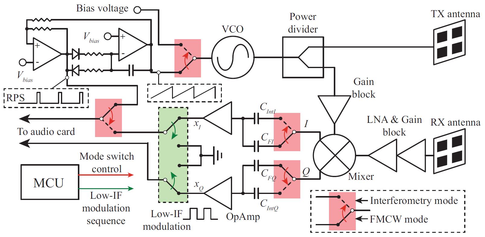
Fig. 1. Block diagram of the 5.8-GHz multi-mode radar prototype
Fig. 1 is the block diagram of the 5.8-GHz multi-mode radar prototype. To simplify the system complexity and minimize its cost, the two radar modes are realized to share the same RF components and signal paths. In addition, at signal acquisition block, the audio card of a laptop is used to sample the baseband signal. On the other hand, the interferometry mode operates at a single frequency of 5.8 GHz. It is known that vital signs, i.e., respiration and heartbeat are extreme low frequency signals, which can be easily blocked by the band-pass filter of an audio card. In this work, a low-intermediate-frequency (low-IF) modulation method is implemented to up-convert the baseband signal to an IF, so that the tiny low frequency vital signs will not be filtered out by the audio card. Note also that the low-IF scheme has advantages in relation to mitigation of flicker noise, which has a higher power level at the around-zero-frequency components of the baseband signal. After data acquisition, envelope detection is here proposed to recover the vital signs in the interferometry mode. The distortion effect of low-IF modulation and the way to optimize the sensitivity of envelope detection are analyzed. Regarding the FMCW mode, a free-running VCO controlled by a simple operational-amplifier-based circuit is used to generate the desired frequency-modulated RF signal. By acquiring the baseband output along with a reference pulse sequence (RPS), which is locked to the sawtooth signal, the coherence property of the radar can be achieved.
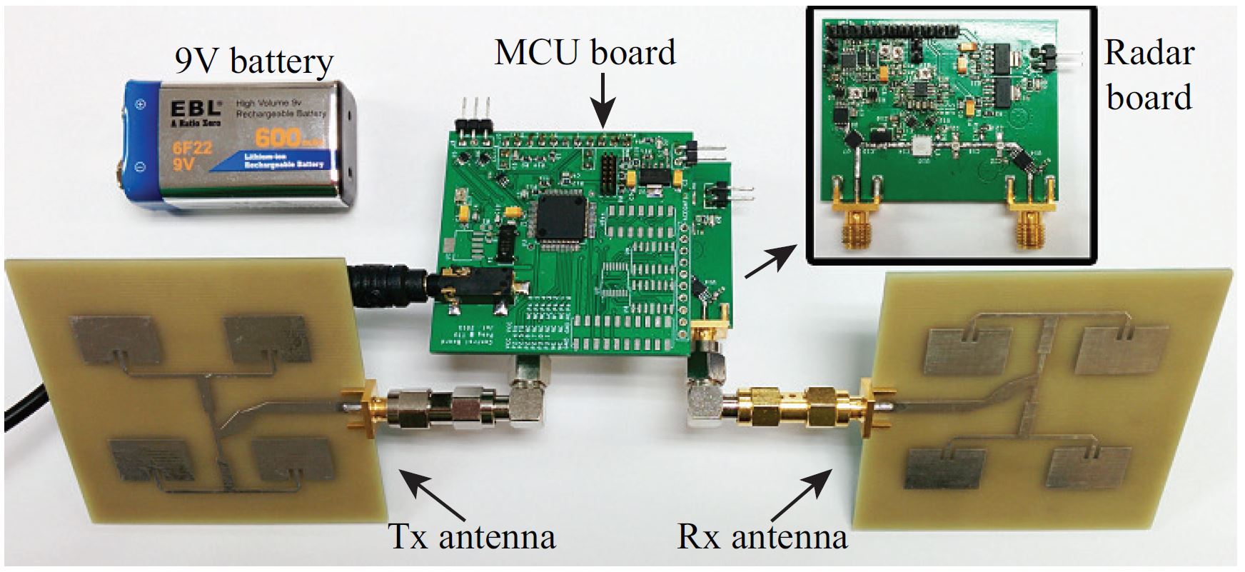
Fig. 2. Photo of the 5.8-GHz multi-mode radar prototype
Fig. 2 details the photo of the implemented radar system. The prototype consists of two PCBs stacked together. The upper one is the board with a MSP430 micro-controller and the lower one is the radar board, which integrates the sawtooth and reference generator, radar front-end, and the baseband amplifiers. The total size of the radar system is 50 mm × 60 mm × 20 mm. As radiating sub-systems, 2 × 2 or 4 × 4 patch antennas are used in the different experiments. The gain of the 2 × 2 array is 11.3 dB and the half-power beam width is 46 degrees. The gain of the 4 × 4 array is 16.3 dB and the half-power beam width is 21.6 degrees.
Experiments
In this section, experiment results of different applications with the customized 5.8-GHz radar are demonstrated.
Short-range localization
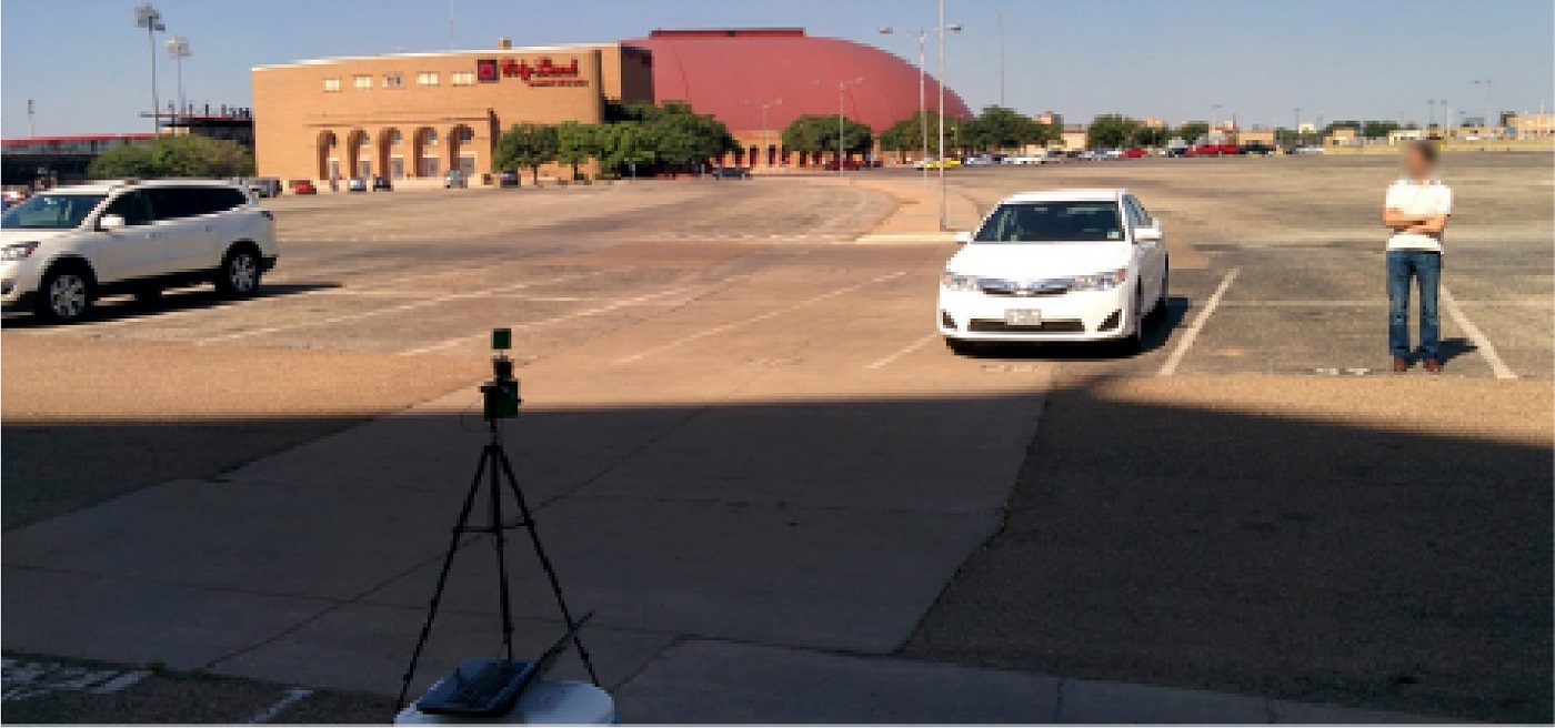
Fig. 3. Experimental setup for a two-dimensional scan
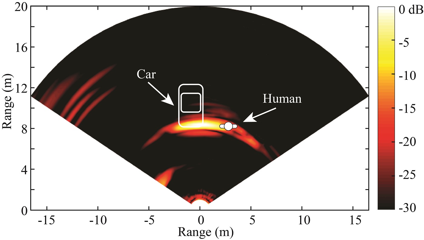
Fig. 4. 2-D mapping result for the scenario
Short-range localization experiment was demonstrated with mechanical rotation of the radar. Fig. 3 shows the photo of the experiment setup. Fig. 4 represents the two-dimensional mapping of the measured range profiles. A large echo detected at the distance of about 8 m is observable, which corresponds to the location of the car and the stationary human. The reason that these two targets are overlapped in the 2-D mapping plot must be found in the limited antenna directivity, which corresponds to a 21.6 degrees beamwidth. In other words, the angular resolution is not high enough to differentiate the human subject from the car. Since the radar prototype is portable, it is almost impossible to achieve an extremely-narrow beamwidth with a highly-constrained antenna size. The other returns on the left of Fig. 4 correspond to the signatures of other stopped cars in the parking lot.
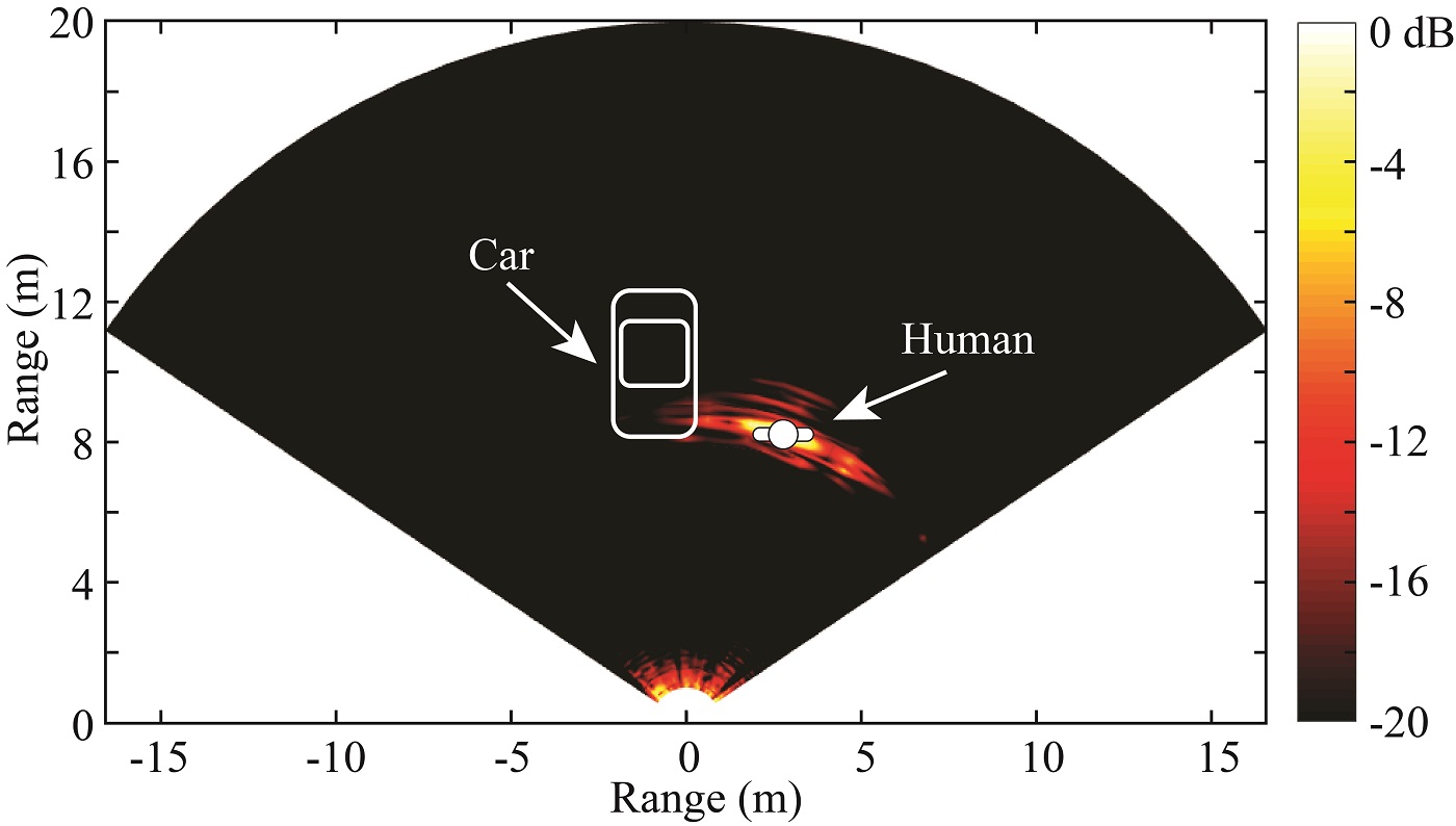
Fig. 5. Human target identification for the 2-D mapping experiment
Even though the angular resolution of the proposed portable radar is not high enough to differentiate the adjacent human target and the car, it is still possible to pinpoint the human subject and eliminate the other stationary clutter returns based on the human “vital-Doppler” effect. After calculating the standard deviation of different measurements in each direction, the differentiate 2-D mapping in Fig. 5 has been obtained. Except for the human target, all the signatures of the stationary targets, including the parked car with running engine, are suppressed. This experiment reveals the ability of the proposed radar sensor to discriminate stationary human subjects in a complex environment.
Range-Doppler imaging
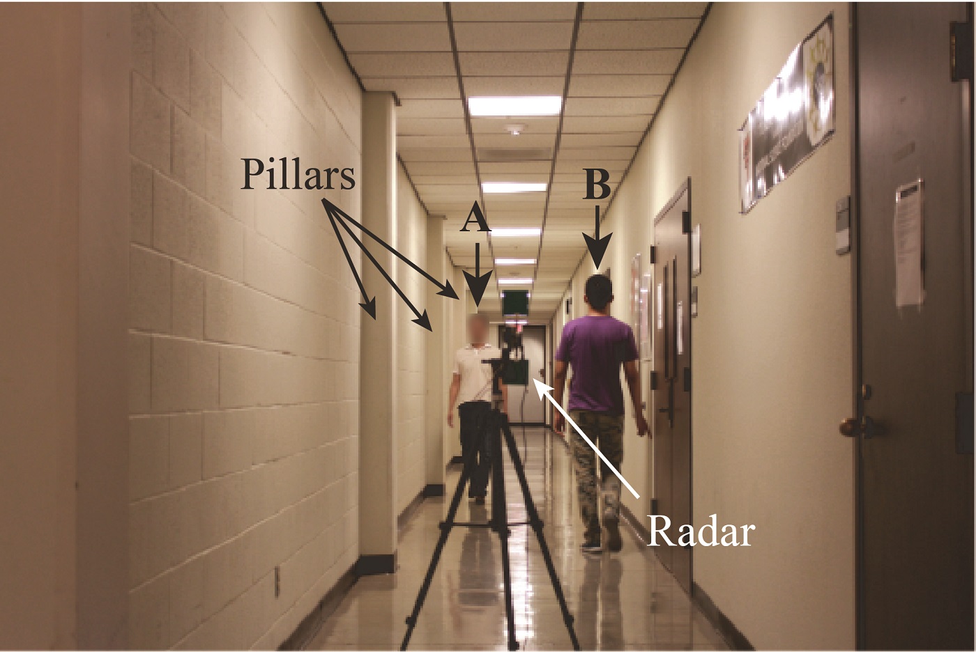
Fig. 6. Photo of the experimental environment for ISAR video production
In this experiment, the portable prototype was used to illuminate two human subjects walking in opposite directions in front of the radar in a corridor. The experiment setup is shown in Fig. 6. The corridor is quite narrow with walls and many pillars, which cause a lot of clutter returns.
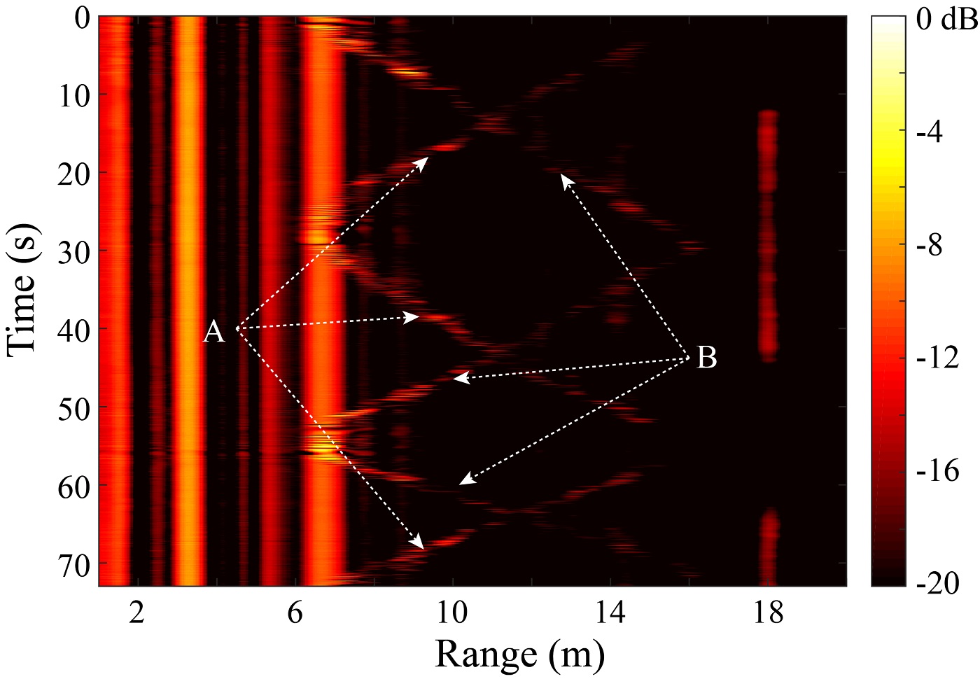
Fig. 7. Range-profile matrix for two human subjects walking in opposite directions in a narrow corridor
Fig. 7 shows the range-profile matrix for the experiment in a 73-s CPI. Many strong vertical strips, which correspond to the stationary objects, can be observed in Fig. 7. Also, the traces of the two moving human subjects are noticeable, but are much weaker than the stationary clutter returns.
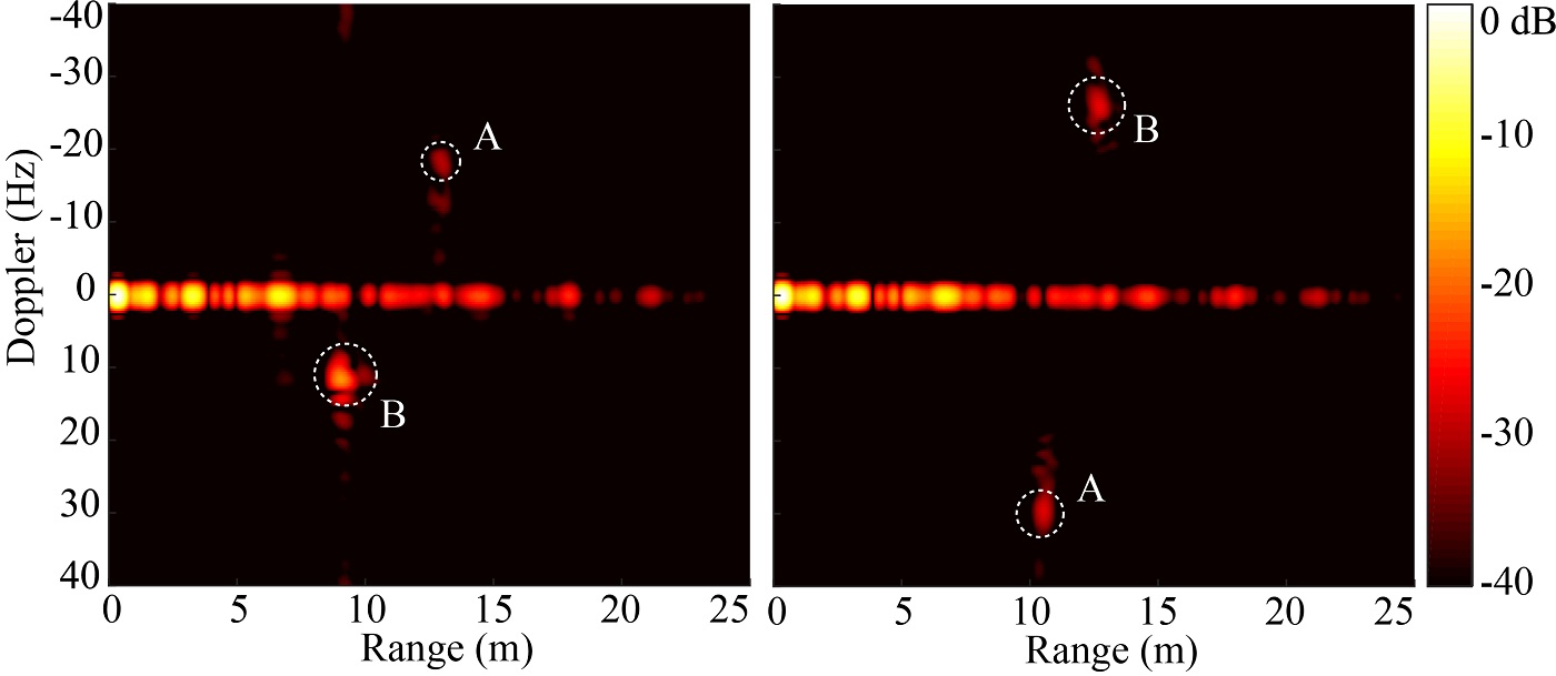
Fig. 8. Frames of range-Doppler imaging
The range-Doppler images in Fig. 8 provide the proposed portable radar with 2-D isolation and tracking capabilities by combining together the Doppler information and the absolute ranging. This could be leveraged for radar-based short-range tracking for healthcare or driver-less vehicle applications.
Structural healthiness monitoring
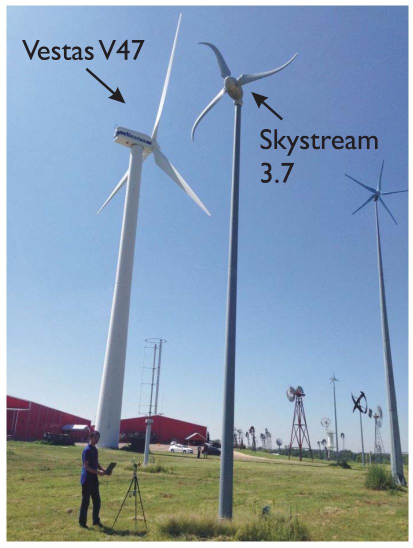
Fig. 9. Photograph of the illuminated wind-turbine acquisition scenario in the American Wind Power Center, Lubbock, TX, USA
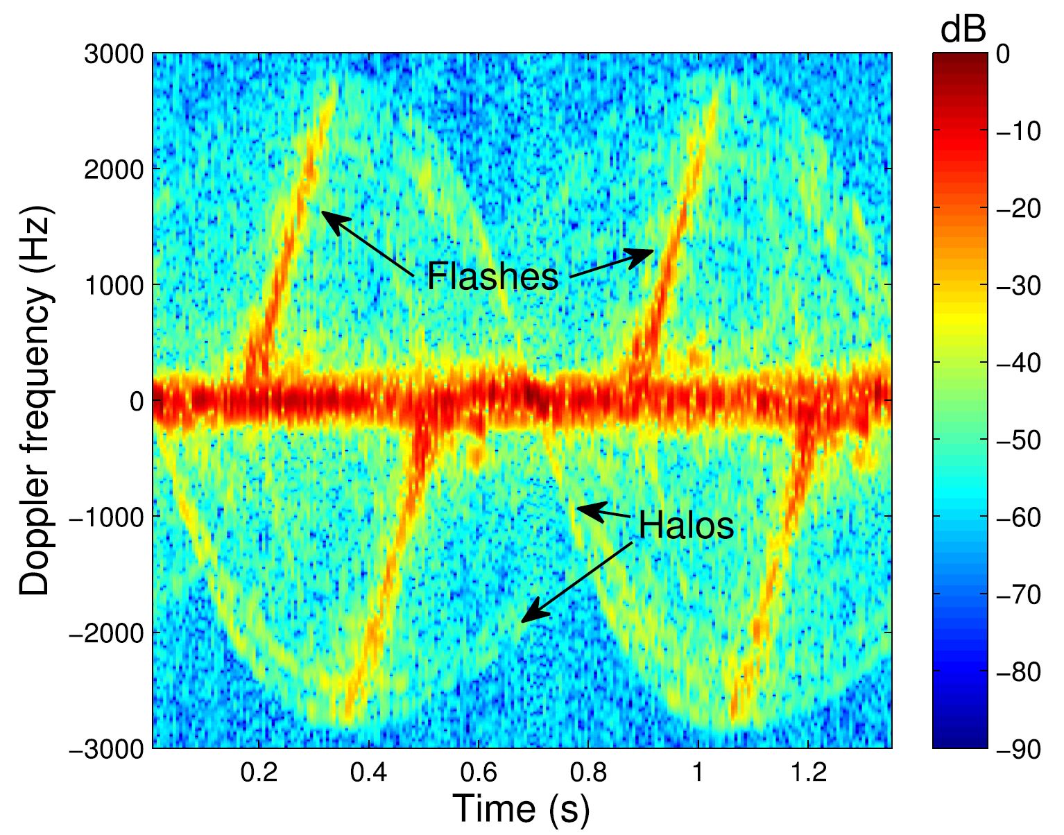
Fig. 10. Spectrogram for the Vestas V47 wind turbine illuminated by the radar prototype
This radar prototype was employed in the American Wind Power Center, Lubbock, TX, USA, to monitor the structural healthiness the wind turbines. In the American Wind Power Center, many wind turbines with various sizes, number of blades, horizontal and vertical rotation axes, and so forth are available. A photograph of the in-field wind-turbine acquisition scenario is provided in Fig. 9. Fig. 10 illustrated the spectrogram for the Vestas V47 wind trubine and these results may be exploited for monitoring purposes.
Fall detection
Falls are among the leading causes of fatal and non-fatal injuries for seniors. The 5.8-GHz prototype of portable radar was used in the experiments of fall detection.
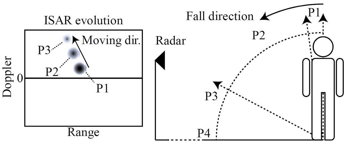
Fig. 11. Illustration of the actions of a human subject and the corresponding range-Doppler image evolutions
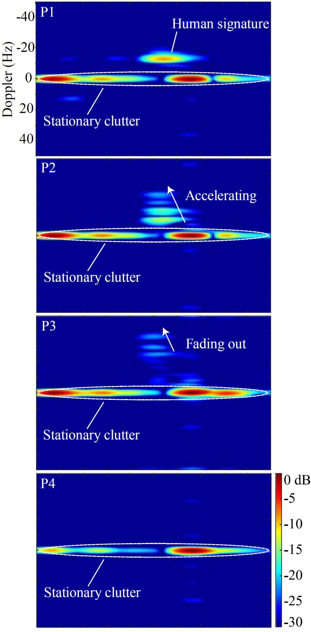
Fig. 12. Corresponding range-Doppler images of a fall incident
Fig. 11 illustrates the case when the human subject falls toward the radar. The falling event is divided into four phases depending on the changes of the velocity, RCS, and range of the human subject. The corresponding range-Doppler images are shown in Fig. 12. This work has demonstrated the ability of an FMCW radar to detect fall events based on real-time range-Doppler imaging.
Related Publications:
- Z. Peng, J.-M. Muñoz-Ferreras, Y. Tang, R. Gómez-García, L. Ran, and C. Li, “A portable FMCW-interferometry radar with programmable low-IF architecture for localization, ISAR imaging and vital-sign tracking,” IEEE Transactions on Microwave Theory and Techniques, vol. 65, no. 4, pp. 1334-1344, Apr. 2017.
- J.-M. Muñoz-Ferreras, Z. Peng, Y. Tang, R. Gómez-García, D. Liang, and C. Li, “Short-range Doppler-radar signatures from industrial wind turbines: theory, simulations, and measurements,” IEEE Transactions on Instrumentation and Measurement, vol. 65, no. 9, pp. 2108–2119, Sep. 2016.
- Z. Peng, J.-M. Muñoz-Ferreras, C. Li, and R. Gómez-García, “An FMCW Radar Sensor for Human Gesture Recognition in the Presence of Multiple Targets,” in IEEE International Microwave Bio-Conference (IMBioC), Göteborg, Sweden, May 15-17, 2017.
- J.-M. Muñoz-Ferreras, Z. Peng, Y. Tang, R. Gómez-García, and C. Li, “Doppler-Radar-Based Short-Range Acquisitions of Time-Frequency Signatures from an Industrial-Type Wind Turbine,” in IEEE Wireless Sensors and Sensor Networks (WiSNet), Phoenix, AZ, Jan. 15-18, 2017.
- Z. Peng, J.-M. Muñoz-Ferreras, R. Gómez-García, and C. Li, “FMCW radar fall detection based on ISAR processing utilizing the properties of RCS, range, and Doppler,” in IEEE International Microwave Symposium (IMS), San Francisco, CA, May 22-27, 2016.
0 Comments