Introduction
In this project, a K-band portable FMCW radar with beamforming array was built. This is the first PCB realization of short-range localization radar with beamforming capability with a range of ±45° in K-band. The phase control for the radar system was realized simply by microwave structure and PIN diodes. As PCB implementation of K-band radar inevitably suffers from errors due to component variation and mismatch, soldering and fabrication error, a calibration method is proposed and experimentally shown as effective for the proposed K-band portable radar system. With the proposed system, it is possible to form more complex beam patterns based on the proposed solution, since the vector controller can simultaneously control both the phase and amplitude of K-band signals.
System Design
Schematic
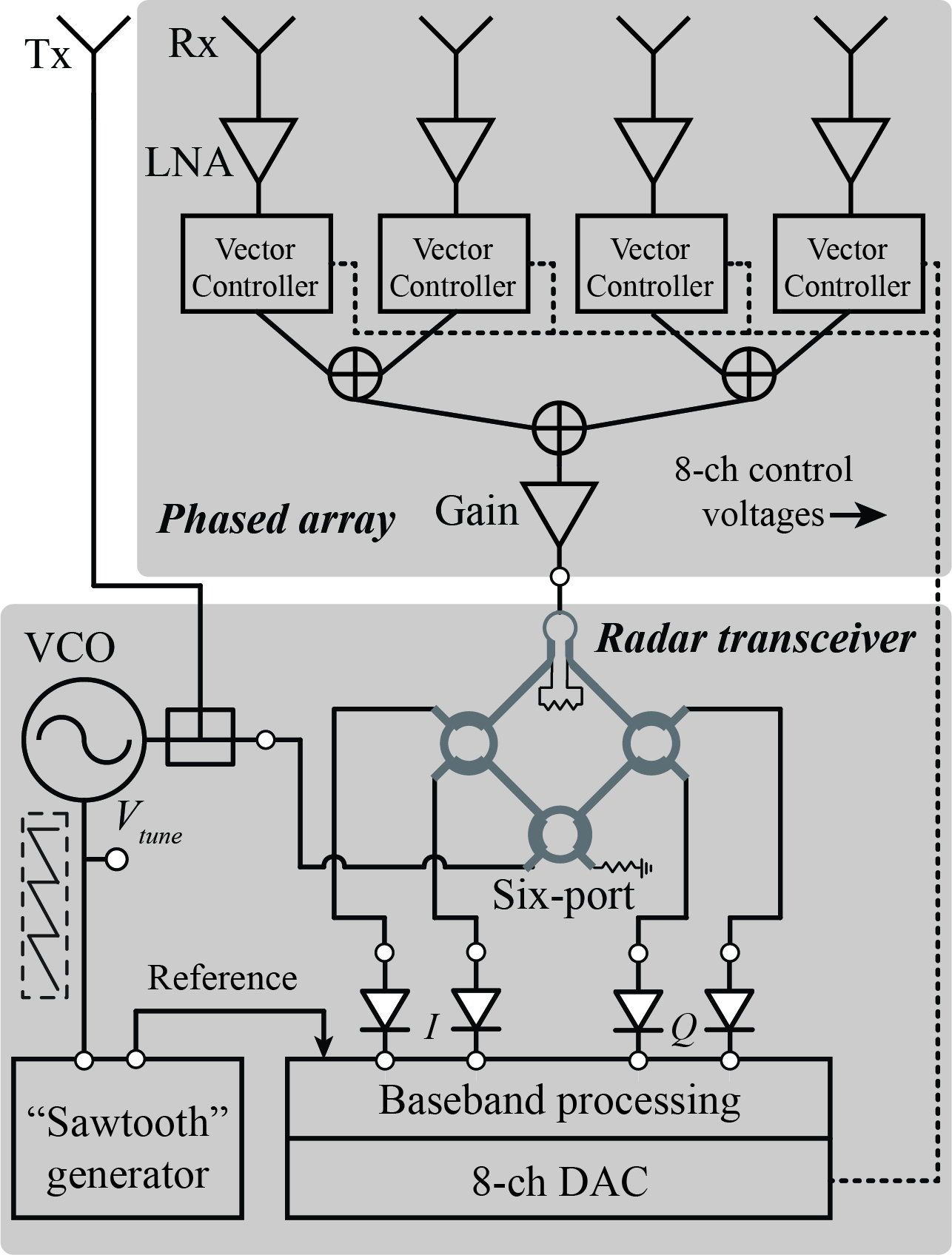
Fig. 1. Block Diagram of the 24 GHz Phased Array Radar
Fig. 1 is the block diagram of the whole radar system. This radar system includes both the transmitter and receiver channels. The transmitter channel consists of a VCO and a single patch antenna. A “sawtooth” voltage generated by an operational-amplifier-based circuit is used to control the VCO to generate a frequency-modulated RF signal from 23.5 GHz to 24 GHz. The receiver channel consists of a beamforming array, a six-port circuit and a baseband circuit.The beamforming array is a four-element linear array. Each element is a series-fed microstrip patch array antenna. The beam of the array can be continuously steered with a range of ±45° on the H-plane through an array of vector controllers. The vector controller is based on the concept of vector sum. However, different from previous works that are either based on integrated circuits or bulky modules, this design realizes the concept in K-band by simple microwave structure and PIN diodes on a printed circuit board (PCB). Each vector controller is capable of controlling the phase and the amplitude of the corresponding array element of the four-element linear array. The beat signal of the FMCW radar is detected by the six-port circuit and then sampled by the soundcard of a laptop. The whole radar system is fabricated on PCB.
Hardware
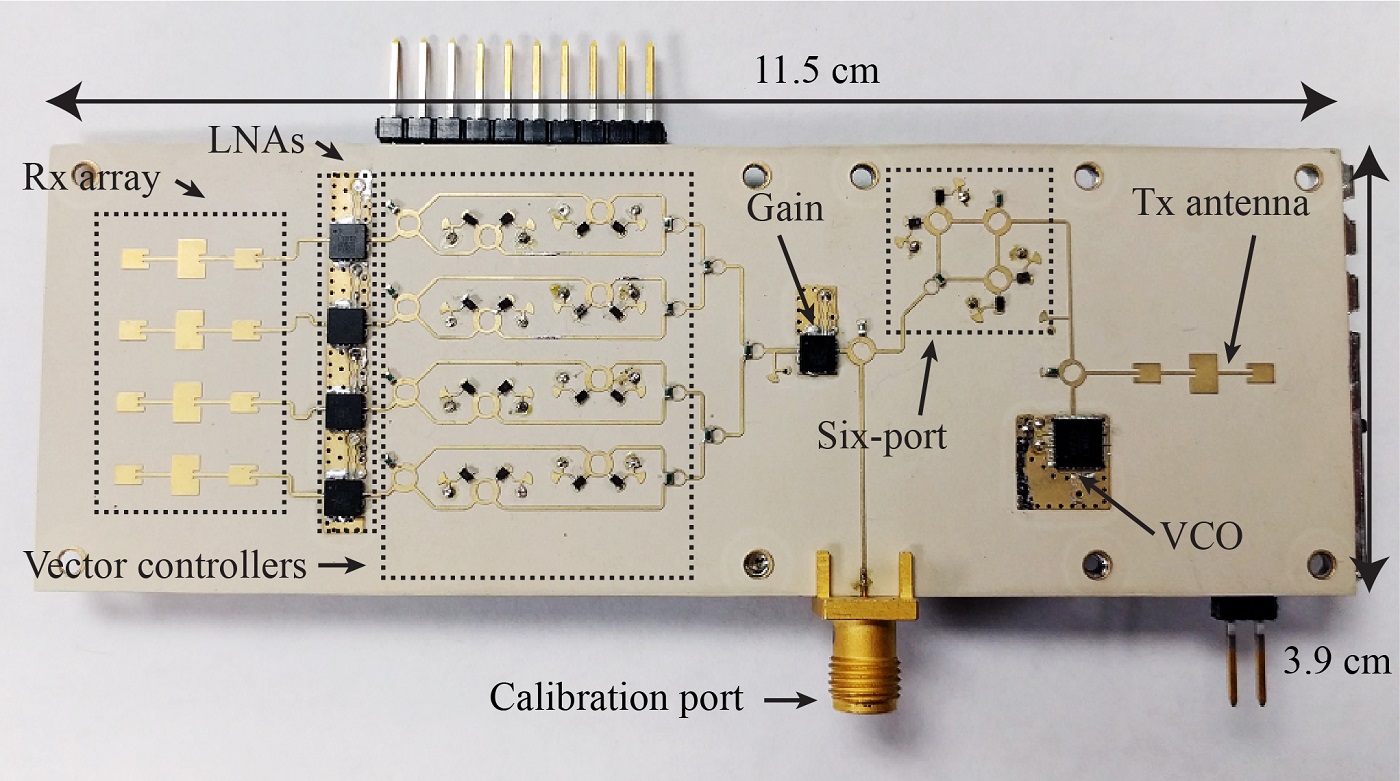
Fig. 2. 24 GHz Phased Array Radar Prototype
The photo of the prototype is shown in Fig. 2. The entire radar prototype has a size of 11.5 cm × 3.9 cm and weighs 69 grams. The substrate material used for the RF board is Rogers RO3006 and the substrate material for the baseband board is FR4. In the beamforming array, the LNAs are MACOM MAAL-011111, and the PIN diodes are Skyworks SMP1302. In the FMCW radar transceiver part, the VCO is Analog Devices HMC739LP4, the gain block is MACOM MAAL-011111, and the Schottky diodes are Skyworks SMS7621-040LF. The main components in the baseband are the operational amplifiers (Analog Devices ADA4851) and the DAC (Analog Devices AD5668).
Experiment
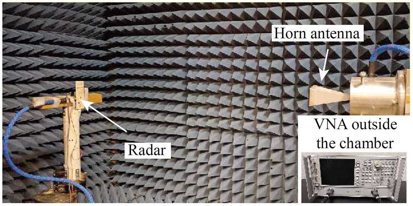
Fig. 3. Radar Prototype Test in the Microwave Anechoic Chamber
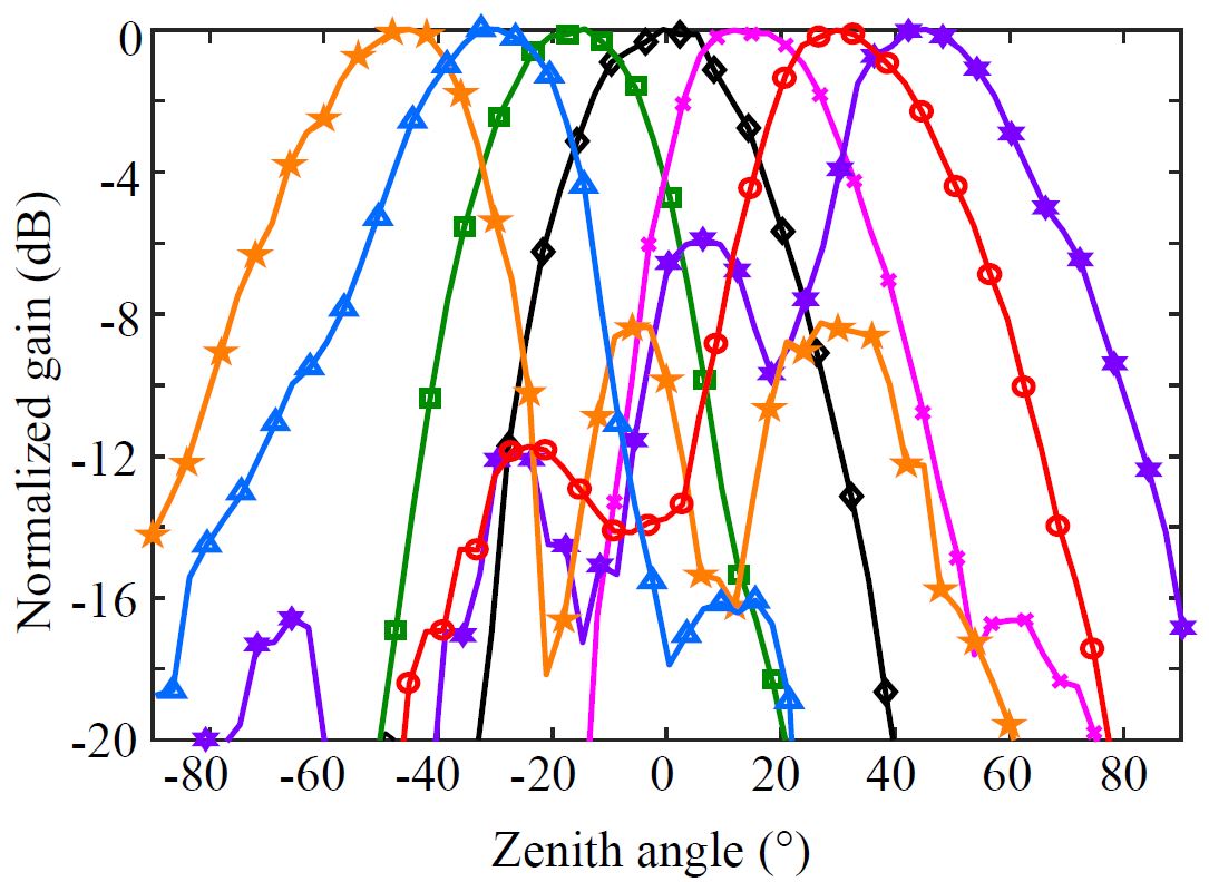
Fig. 4. Measured Patterns of the Beamforming Array Steered to -45°, -30°, -15°, 0°, 15°, 30°, and 45°
Experiments have been taken to measure the far-field patterns of the beamforming array with different steering angles by changing the phase shift of the vector controllers. The measurement setup photo is shown in Fig. 3. The measured patterns of the beamforming array steered to different angles are illustrated in Fig. 4.
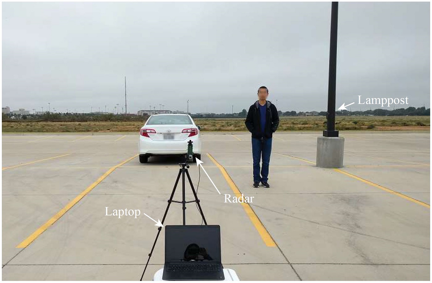
Fig. 5. Radar Prototype Field Test
Fig. 5. is the photo of the field test setup. In the field test, a car and a lamppost were in the radar’s field of view. The scanning angle of the radar started from -45° to 45° with a step size of 2.5°. The radar system was powered by a single 9-V battery.
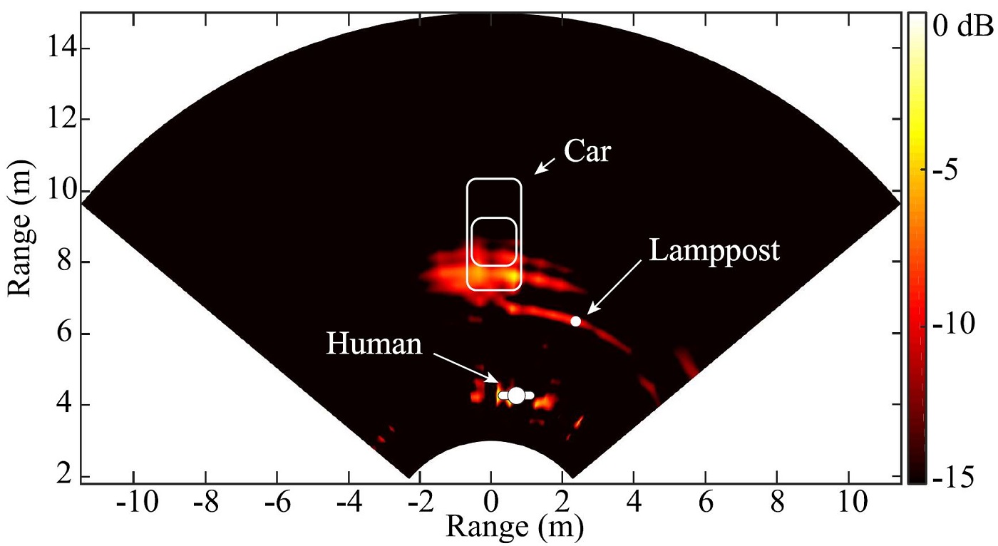
Fig. 6. Radar Measurement Result
As shown in Fig. 6, signatures of the car, the lamppost and the human subject can be clearly seen. It should be noted that the signature of the human subject is not consistent, because of the vital-Doppler effect.
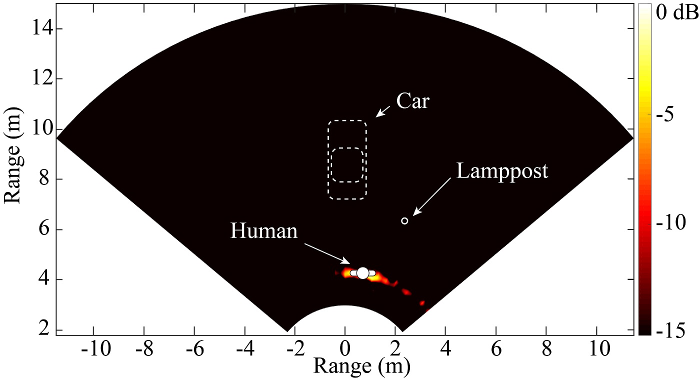
Fig. 7. Human Target Identification Result
To identify the human subject, 10 sequence of FMCW scans were performed and the standard deviation of the detected range spectrum was drawn in Fig. 7. With this method, the signatures of the car and the lamppost are suppressed and the human signature can be extracted, achieving human-aware localization.
Related Publications:
- Z. Peng, L. Ran, and C. Li, “A κ-band portable FMCW radar with beamforming array for short-range localization and vital-Doppler targets discrimination,” IEEE Transactions on Microwave Theory and Techniques, vol. 65, no. 9, pp. 3443-3452, Sept. 2017.