This was the project for my Master Thesis. Some parts of the project have been published in IEEE Antennas and Wireless Propagation Letters and IEEE Transactions on Microwave Theory and Techniques.
Introduction
In this work, a new concept “complex domain” radio frequency (RF) frontend is proposed, the relatively slowly changed waveform delay information required to accomplish adaptive beamforming can be separated from wideband RF signals, based on which a self-contained beamforming system can be implemented with a low-speed baseband. By introducing vector RF multipliers in the proposed frontend, the amplitude and phase of RF signals can be simultaneously controlled by the real and imaginary parts of complex numbers, such that beamforming algorithms derived in complex domain can be directly applied without any form of transformation. By doing so, the massive use of conventional T/R modules and high-speed baseband devices can be avoided. This method is able to significantly simplify the realization and decrease the cost of wideband digital beamforming systems, and can be widely used in low cost, power efficient beamforming applications.
Design
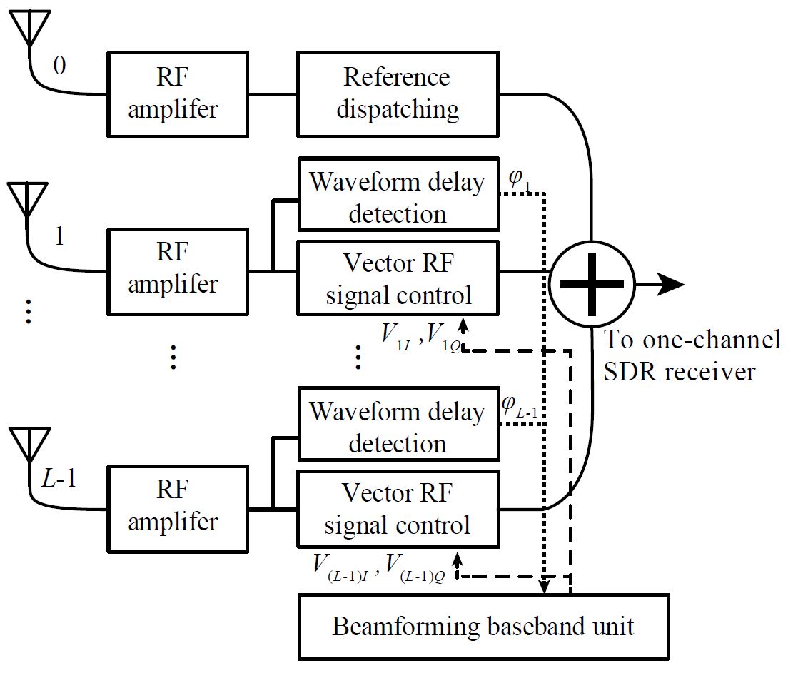
Fig. 1. Block diagram of the proposed architecture of an RF domain beamforming system
Fig. 1 shows the proposed block diagram for the proposed system. Firstly, RF amplifiers are used to replace the T/R modules, to provide gains to all the received signals. The amplified RF signal in channel 0 is used as the reference signal, and the waveform delays between this reference signal and the other RF signals received by different antenna elements can be obtained by wideband waveform delay detectors. In the meantime, vector multipliers are used to implement simultaneous control to the amplitude and waveform delay of each RF signal, performing beamforming in RF domain.
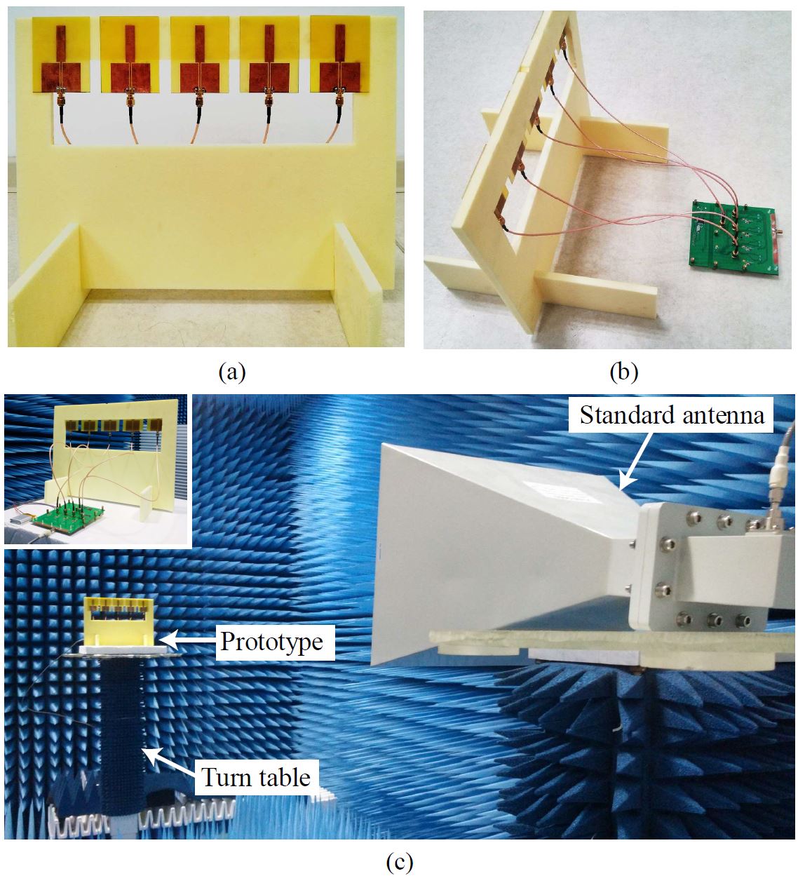
Fig. 2. (a) Five-element linear array. (b) The connection between the linear array and the RF frontend. (c) Experimental setup in the microwave anechoic chamber. Inset shows the prototype powered by a Li-ion battery
Fig. 2(a) shows the photograph of the five-element monopole array, in which neighboring antennas are separated by half a wavelength. The supporter of the array is made of Styrofoam, whose dielectric constant is very close to 1. Fig. 2(b) shows how the array is connected to the RF frontend with coaxial cables. Fig. 2(c) shows the experimental setup in the microwave anechoic chamber.
Related Publications:
- Z. Peng, J. Chen, Y. Dong, B. Zhang, D. Ye, J. Huangfu, Y. Sun, C. Li, and L. Ran, “Radio frequency beamforming based on a complex domain frontend,” IEEE Transactions on Microwave Theory and Techniques, vol. 64, no. 1, pp. 289-298, Jan. 2016.
- Z. Peng, T. Hu, W. Cui, J. Huangfu, C. Li, and L. Ran, “Unconventional beamforming for quasi-hemispheric coverage of a phased array antenna,” IEEE Antennas and Wireless Propagation Letters, vol. 12, pp. 1654–1657, Dec. 2013.