Introduction
This was a team project which aimed to evaluate the possibility and performance of a RF signal generator built with off-the-shelf components. This project has both the hardware the software. The hardware part includes a frequency synthesizer, filter array, modulation circuit, power controller and micro-controller. The software part includes micro-controller code, CPLD code and a control interface on PC. The accomplished prototype has an output frequency ranging from 150 kHz to 3 GHz with 0.1 Hz step. The phase noise of the 2.2 GHz carrier frequency is -84 dBc/Hz at 1 KHz offset and -93 dBc/Hz at 10 KHz offset. The output amplitude can be controlled from -130 dBm to 20 dBm with 0.1 dB step.
Hardware
Tools used to design the hardware
- Agilent ADS: For the design of microstrip filters
- Cadence Capture / OrCAD: For the design of PCB schematic and layout
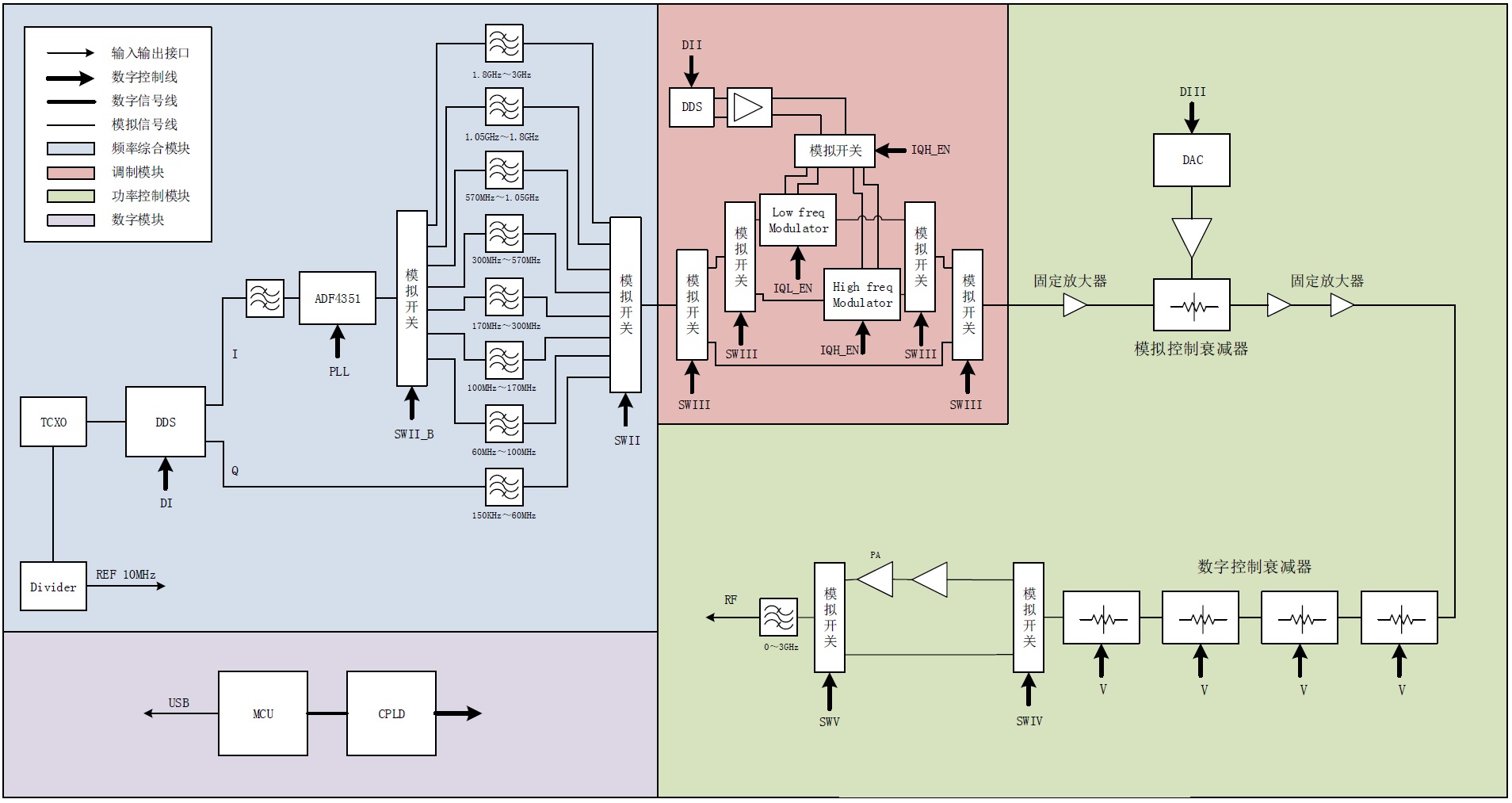
Fig. 1. System block diagram
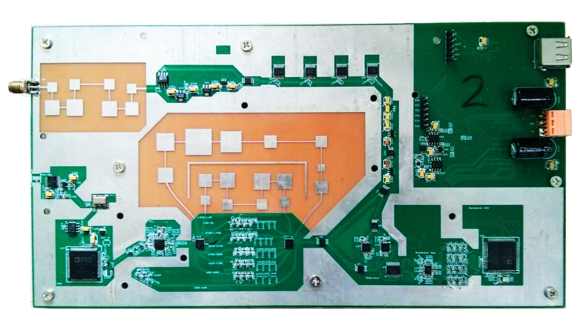
Fig. 2. Photo of the prototype
Software
Micro-controller
- Device: Atmel Atmega88PA
- IDE: AVR Studio
- Language: C
CPLD
- Device: XILINX XC995144XL
- IDE: XILINX ISE Design Suite
- Language: Verilog
PC
- IDE: Microsoft Visual Studio
- Language: C#
0 Comments