
Can a capable RF signal generator be built entirely from off-the-shelf components? This team project set out to find out, and to measure how well such a design performs.
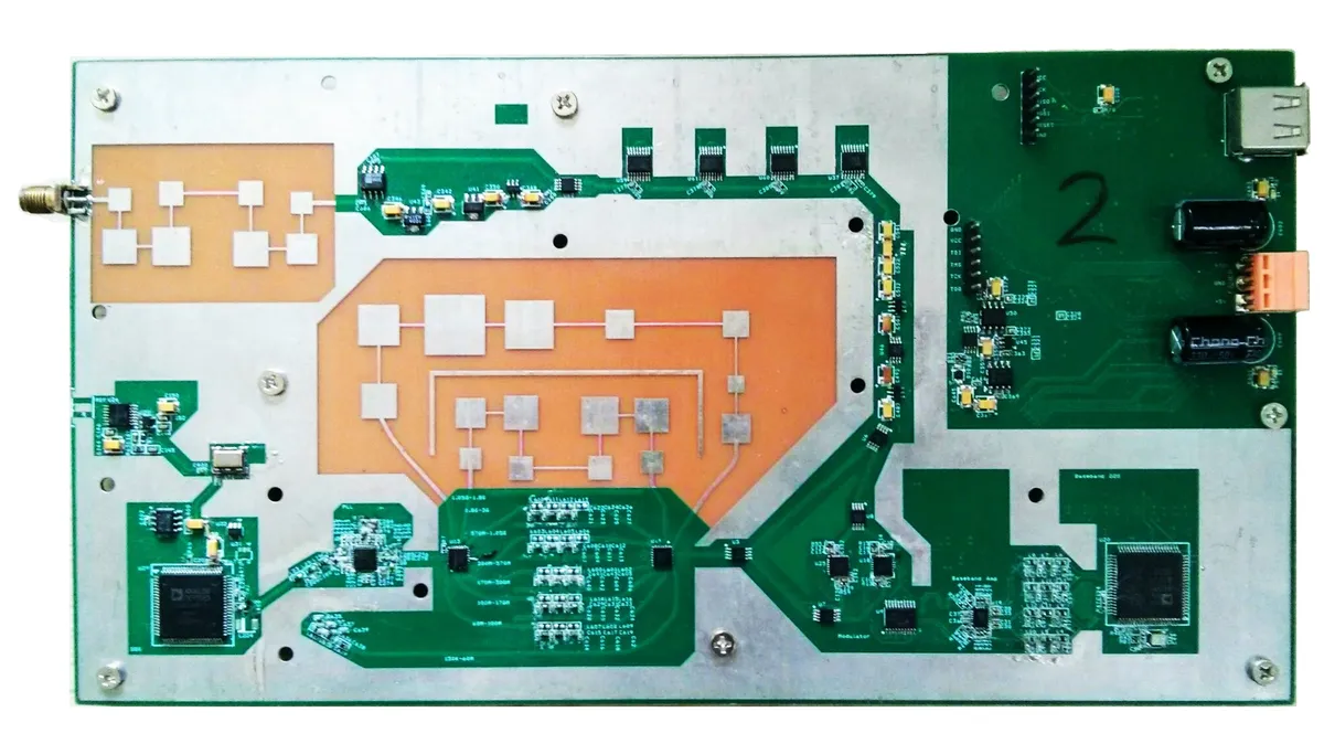
The result covers 150 kHz to 3 GHz in 0.1-Hz steps, with output power adjustable from −130 dBm to +20 dBm in 0.1-dB steps. It is a complete instrument: RF hardware, a microcontroller and a CPLD to run it, and a control program on a PC.
- Frequency range
- 150 kHz – 3 GHz, 0.1-Hz steps
- Output power
- −130 to +20 dBm, 0.1-dB steps
- Phase noise at 2.2 GHz
- −84 dBc/Hz at 1 kHz offset
−93 dBc/Hz at 10 kHz offset
Hardware
Synthesizer, filters, modulation, power control
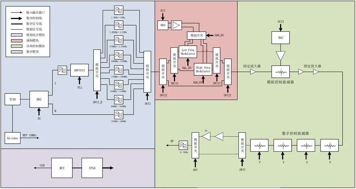
The signal chain (Fig. 2) starts with a frequency synthesizer, followed by a filter array, a modulation circuit, and a power controller, all managed by a microcontroller. The microstrip filters were designed in Agilent ADS, and the schematics and PCB layout in Cadence Capture and OrCAD.
Software
Three layers of control